1. Overview & Operational Problem
Industrial designers and CAD engineers accustomed to injection-molded plastics or sheet metal frequently apply rigid-body modeling rules to inflatable bladder designs. They specify sharp 90-degree outer corners, zero-radius internal cutout slits, and ultra-narrow perimeter borders. When these CAD files are sent to tooling makers, they fail tooling validation or produce bladders that tear immediately upon inflation.

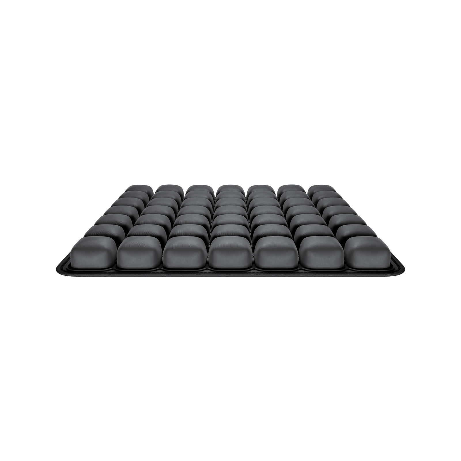
Figure 1: DFM Guidelines for Bladder Perimeter Weld Radii and Stress-Relief Teardrops – Engineering and manufacturing implementation.
2. Engineering Root Causes & Failure Analysis
Flexible pneumatic films behave under continuum membrane mechanics: stress concentrations that are harmless in rigid solids become catastrophic failure points in thin elastomeric films. Adhering to proven Design for Manufacturability (DFM) rules during initial CAD modeling eliminates tooling modifications and ensures robust high-frequency welding yield.
1. External Perimeter Corner Fillet Rules
Sharp outside corners cannot be welded reliably. An outside corner must have a minimum radius of $R \ge 5.0\text{mm}$ (preferably $\ge 10.0\text{mm}$). Sharp external corners cause dielectric field concentration and leave razor-sharp flash corners that puncture neighboring bladders during bulk packaging.
2. Internal Slit Terminations: The Mandatory Teardrop Relief
When an ergonomic cushion design requires internal cutouts or slit openings to wrap around user anatomy, the weld seam must never terminate in a sharp point. Under inflation, peel stress at a sharp termination approaches infinity. The seam must end in a circular teardrop or full round boss ($R \ge 6.0\text{mm}$) with an enlarged weld land to dissipate peel forces.
3. Weld Flange Width and Trim Margins
For bladders operating between 0.5 and 2.5 PSI, nominal perimeter weld seam width should be designed at $4.0\text{mm} \pm 0.5\text{mm}$. The raw film trim margin (the un-welded selvage edge outside the seam) must maintain at least $1.5\text{mm}$ to prevent the die cut from nicking the airtight weld boundary.
3. DFM Parameters & Verification Matrix
| CAD Feature | Common Design Flaw | Mandatory DFM Design Rule | Failure Prevented |
|---|---|---|---|
| Outside Perimeter Corner | Sharp 90° corner (R < 1mm) | Design external radius R ≥ 5.0mm | Dielectric arc blowout and carton puncturing |
| Internal Slit Termination | V-shaped sharp slit end | Incorporate circular teardrop boss (R ≥ 6mm) | Immediate seam tear under passenger loading |
| Perimeter Weld Seam Width | Narrow seam (< 2.0mm to save space) | Specify 3.5mm - 5.0mm nominal weld land | Peel rupture during burst pressure testing |
| Valve Flange Proximity | Valve edge < 5mm from perimeter weld | Maintain minimum 15mm clearance from seams | Tooling collision and film pinching during RF cycle |
| Internal Baffle Pitch | Baffles spaced too close (< 25mm) | Maintain pitch ≥ 1.5x inflated cell height | Restricted air transfer and rigid hard spots |
4. Frequently Asked Questions (FAQ)
Q: Why do internal cutouts require larger radii than exterior borders?
A: Because internal cutouts experience direct tensile hoop stresses pulling in opposite directions, whereas exterior borders are supported by uniform internal head pressure.
Q: Can teardrops be added after the tooling is cut?
A: No. Modifying an internal teardrop requires re-milling the brass electrode or welding a patch, which compromises tool flatness and platen grounding.
5. Actionable Next Steps for Technical Teams
Upload your native 3D CAD files to Airjour for an automated DFM geometric review and seam-integrity audit.