1. Overview & Engineering Context
For product developers, mechanical engineers, and Supplier Quality Engineers (SQEs) developing pneumatic comfort hardware—such as ergonomic seat cushions, adjustable sleep surfaces, and postural lumbar supports—slow pressure loss is one of the most frustrating failure modes to resolve. Unlike macro-punctures or catastrophic seam ruptures that produce immediate streams of bubbles during standard submerged water-dunk inspections, slow pressure decay occurs incrementally over days or weeks. A cushion that leaves the factory line meeting firmness specifications may feel noticeably soft after sitting in a distribution warehouse or after several nights of static hold.

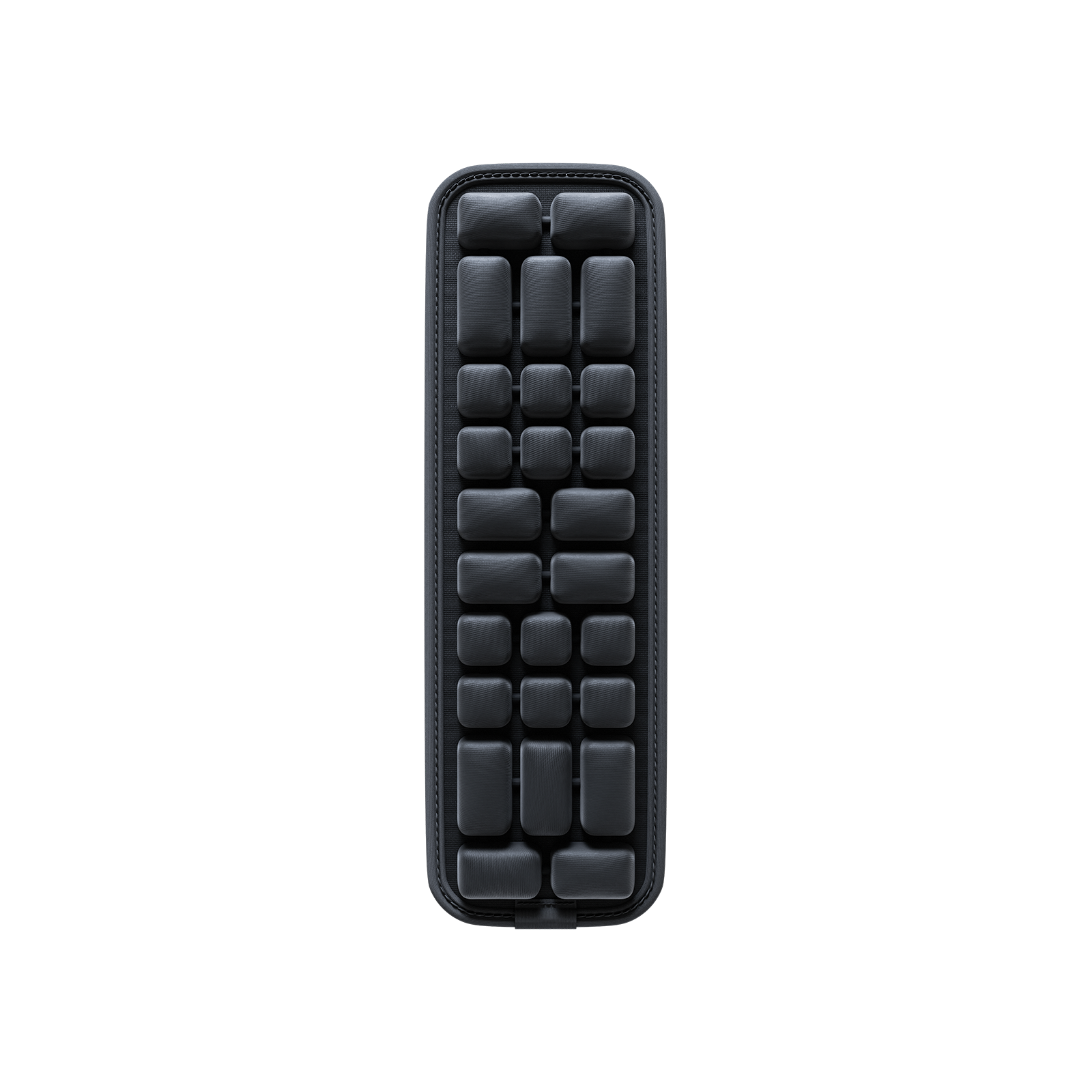
Figure 1: Diagnosing Slow Pressure Decay in Inflatable Comfort Products: Physical Mechanisms, Tooling Root Causes, and Quality Mitigation – Industrial design and quality implementation.
2. Failure Mechanics & Technical Analysis
Before modifying tooling dies or rejecting film lots, engineering teams must verify whether air molecules are physically escaping the bladder, or if thermodynamic contraction and mechanical stress relaxation are producing an apparent drop in gauge pressure. Under Gay-Lussac's Law, pressure changes directly with temperature. Simultaneously, Thermoplastic Polyurethane (TPU) exhibits viscoelastic creep, expanding chamber volume over initial inflation cycles. True pneumatic mass loss traces back to polymer permeability, high-frequency (HF) weld boundary notch thinning, and valve interface distortion.
1. Thermodynamic & Viscoelastic Variables vs True Mass Loss
When an inflatable bladder is inflated with hot compressed air straight from a compressor (e.g., 32°C) to 1.50 PSI gauge, and then cooled to a warehouse ambient of 20°C, Gay-Lussac's Law dictates an immediate physical drop in gauge reading without any gas loss. Furthermore, polymer cold flow causes initial volumetric creep. Quality control procedures must incorporate a pre-conditioning cycle: inflating to a defined pre-stress pressure, stabilizing, exhausting, and re-inflating before initiating static hold logging.
2. Weld Notch Thinning & Micro-Arcing in HF Seams
In High-Frequency (27.12 MHz) welding, the brass electrode applies mechanical clamping force while dielectric excitation melts the polymer. If die penetration is excessive, molten TPU is forced outward into flash, thinning the weld boundary notch below critical design margins. Micro-arcing between the electrode and ground plate can also vaporize sub-20-micron channels that pass 30-second water dunk tests but bleed gas under sustained user loads.
3. Valve Gasket Distortion and Flange Sinking
Welding an injection-molded TPU valve flange to a thin flexible membrane introduces substantial thermal mass asymmetry. Inadequate heat sinking distorts the valve seat, preventing internal silicone flappers or elastomeric stoppers from sealing uniformly. Airborne dust particles as small as 25 microns on the sealing plane can create a persistent micro-bleed pathway.
3. DFM Parameters & Verification Matrix
| Engineering Parameter | Governing Standard | DFM Focus & Risk Analysis | Verification Protocol |
|---|---|---|---|
| Film Thickness Consistency | ASTM D5947 | Gauge drift causes uneven clamp tension and localized weld thinning | Cross-web micrometer roll sampling |
| Film Gas Permeability | ASTM D1434 / ISO 15105 | Sets base molecular barrier limit; polyether transmits faster than ester | Laboratory gas transmission cell audit |
| Weld Notch Retained Thickness | Optical Metrology | Target: Retain specified film stack percentage (≥ 65% nominal thickness per tooling mechanical stops) | 50x micro-polished optical cross-section |
| Dielectric Platen Flatness | Toolmaker Metrology | Non-parallel platens create simultaneous under-weld and over-burn zones | Feeler gauge dial indicator sweep |
| Valve Flange Co-Planarity | Optical Comparator / CMM | Thermal warpage prevents uniform elastomeric gasket seating | Total Indicator Reading (TIR) measurement |
4. Frequently Asked Questions (FAQ)
Q: Why is water-dunk testing insufficient for detecting micro-leaks?
A: Water immersion depends on escaping bubbles detaching from the surface. For leak rates below 1x10^-4 mbar·L/s, surface tension holds forming bubbles in place, allowing micro-defects to pass inspection undetected.
Q: How do engineers distinguish polymer creep from a real leak?
A: By logging pressure in a temperature-controlled room after a standardized pre-stretch cycle. A leaking bladder continues losing pressure linearly, whereas creep exhibits logarithmic decay that asymptotes to a stable baseline.
Q: What role does resin durometer play in air retention?
A: Lower durometer TPUs (e.g., 80A-85A) have higher free volume and chain mobility, exhibiting slightly higher gas diffusion rates and greater initial creep compared to firmer 90A-95A grades.
5. Next Steps for Engineering & Sourcing Teams
Submit your current bladder specifications and weld cross-sections to Airjour for a comprehensive DFM and dielectric stress analysis.