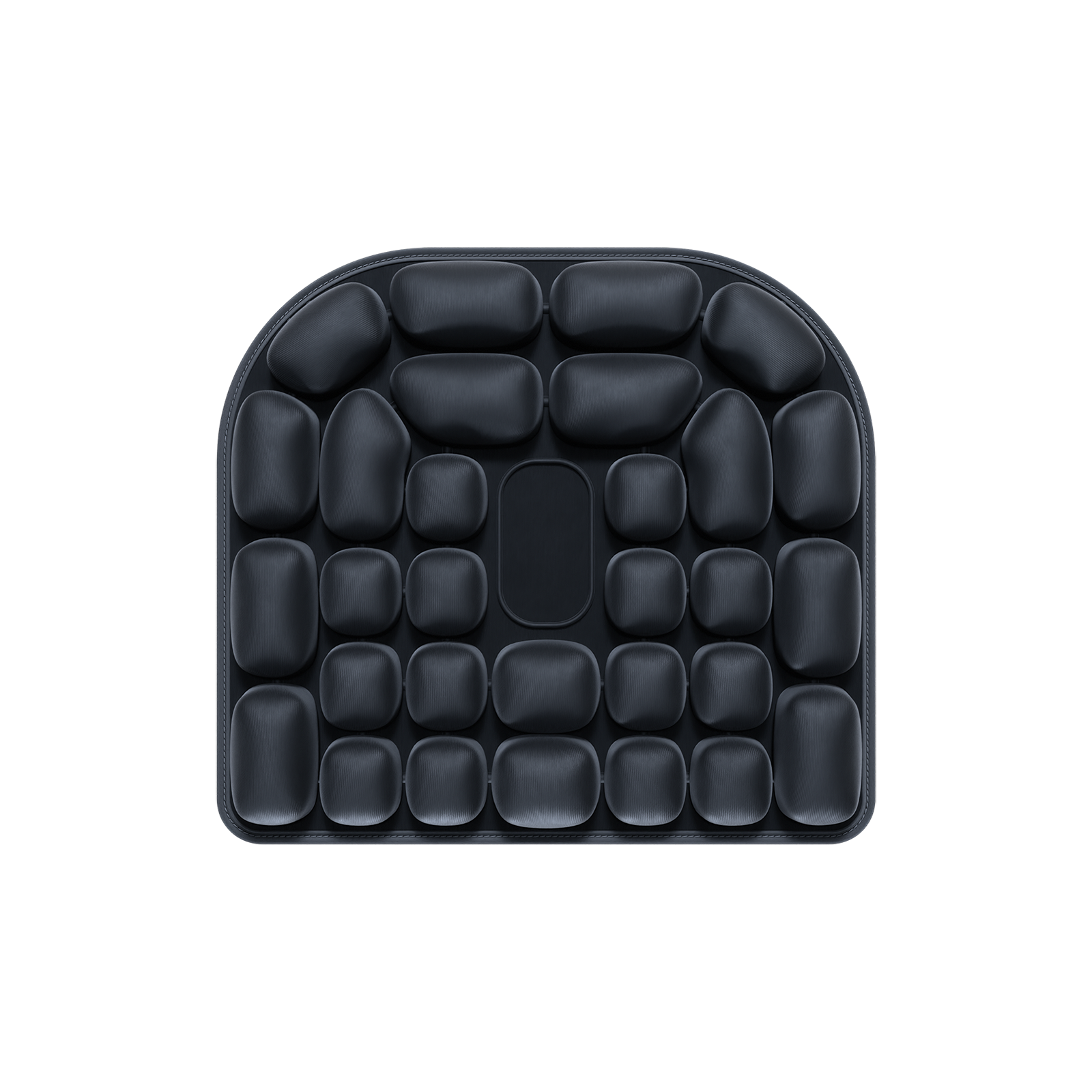
1. Overview & Operational Problem
Procurement teams and category buyers often question why custom High-Frequency (HF) welding tooling requires 6 to 8 weeks of lead time, assuming that a flexible bladder tool is simply a 2D steel die. In reality, precision pneumatic tooling is a multi-disciplinary electro-mechanical system requiring intricate CNC machining, dielectric capacitance balancing, vacuum pick-and-place integration, and iterative thermal shrink compensation.

Figure 1: Factory Lead Time Drivers: Why Inflatable Tooling Cycles Take 45 to 60 Days – Industrial engineering & manufacturing implementation.
2. Engineering Root Causes & Physics of Failure
Understanding the critical path of inflatable tooling fabrication allows sourcing managers to plan realistic New Product Introduction (NPI) timelines, eliminate unforced schedule delays, and avoid costly re-tooling cycles resulting from rushed CAD sign-offs.
1. The Critical Path: From 3D CAD to CNC Brass Electrodes (Weeks 1-3)
Once the engineering drawing is frozen, toolmakers convert the 3D surface model into CAM cutter paths. Precision machining of solid brass or aircraft-grade aluminum electrodes for multi-cell comfort bladders requires 5-axis high-speed CNC milling. Internal baffle steps, vacuum routing holes, and corner fillets must be machined to tight planar tolerances across platen areas often exceeding 800mm x 600mm.
2. Dielectric Tuning and Press Integration (Weeks 4-5)
A newly machined tool must be electrically matched to the factory's 27.12 MHz RF generators. Toolmakers balance the capacitance of the die against ground plates, machine copper busbars, and install solid-state arc suppression sensors. Initial trial pressing identifies cold spots or excessive electric field concentration along complex curves.
3. Thermal Shrinkage Compensation and T1 Qualification (Weeks 6-8)
Thermoplastic films shrink as they cool under platen clamping pressure. Depending on resin durometer and orientation, shrinkage ranges between 0.8% and 2.5%. If the post-weld inflated dimensions fall outside allowable engineering limits, the electrode must be micro-adjusted or re-cut, followed by complete First Article Inspection (FAI) testing.
3. DFM Parameters & Sourcing Verification Matrix
| Tooling Phase | Typical Duration | Core Engineering Activity | Risk of Rushing |
|---|---|---|---|
| Phase 1: DFM & CAM | 5 - 7 Business Days | Corner filleting, shrink calculation, vacuum port layout | Uncorrectable geometry errors in raw tooling |
| Phase 2: CNC Milling | 12 - 16 Business Days | 5-axis brass machining, surface grinding, polishing | Tooling chatter marks and micro-burr arcing |
| Phase 3: RF Matching | 5 - 8 Business Days | Capacitor tuning, grounding setup, bed parallelism | Dielectric blowouts and cold weld seams |
| Phase 4: T1 Sampling & FAI | 7 - 10 Business Days | 100-unit trial run, burst test, 72-hr pressure hold | Mass production yield failures in final goods |
4. Frequently Asked Questions (FAQ)
Q: Can inflatable tooling lead times be expedited safely?
A: Lead times can be compressed by 10 to 14 days by utilizing pre-machined modular baseplates and standardizing valve mountings, but electrical tuning and FAI soak tests cannot be bypassed without severe quality risk.
Q: Why does multi-cavity tooling take longer to fabricate?
A: Multi-cavity tools require strict platen parallelism across all cavities simultaneously; a 0.05mm deviation between cavity 1 and cavity 4 will cause uneven weld penetration across the batch.
5. Actionable Next Steps for Technical Teams
Engage Airjour early in your design phase to parallel-track DFM reviews and compress your tooling lead time.