1. Overview & Operational Problem
During a high-volume manufacturing run of 5,000 dual-chamber ergonomic backrests, end-of-line quality audits detected a catastrophic 22% failure rate during 24-hour differential pressure decay testing. Strangely, the incoming TPU film passed all tensile and barrier inspections, and the High-Frequency generator was outputting stable power. The defect was baffling: bladders produced in Cavity 1 held pressure flawlessly, while bladders produced in Cavity 2 consistently leaked.

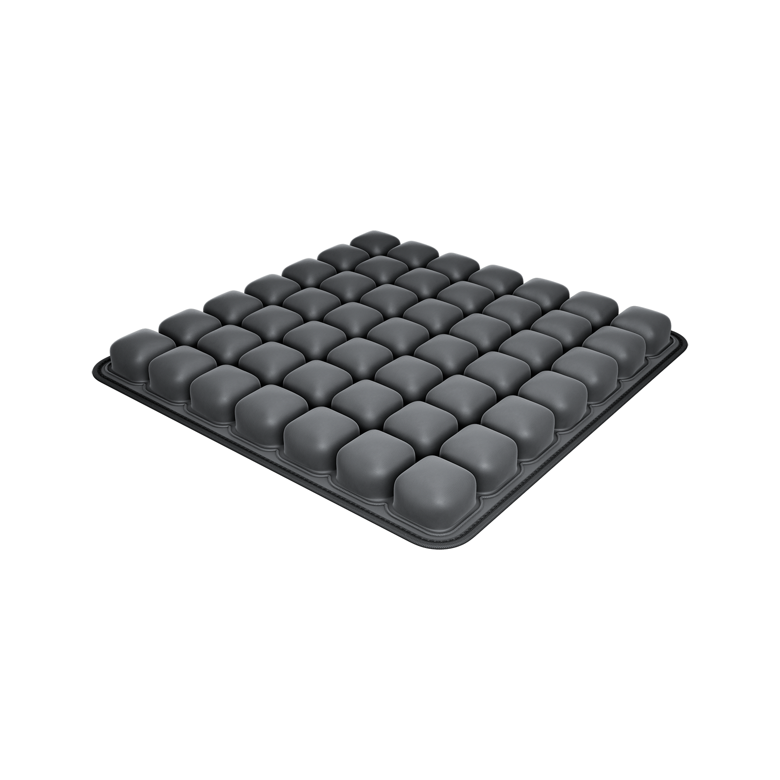
Figure 1: Teardown of a Mass Production Batch Reject: Uneven Electrode Thermal Dissipation – Industrial engineering & quality implementation.
2. Engineering Root Causes & Failure Analysis
A multidisciplinary engineering teardown was initiated to conduct failure forensics. Using thermal imaging, optical weld cross-sectioning, and toolroom metrology, the investigation uncovered a hidden tooling design flaw: severe asymmetric thermal mass dissipation within the multi-cavity lower fixture plate.
1. Thermal Imaging Mapping of Active RF Tooling Platens
Infrared thermography during continuous cycling revealed that Cavity 1 maintained a steady platen temperature of 28°C due to proximity to the main chilled-water inlet. Cavity 2, located at the end of the cooling circuit near a solid steel mounting bracket, experienced heat accumulation reaching 52°C after two hours of continuous cycling.
2. The Impact of Heat Buildup on Weld Seam Thickness
Because the lower tool under Cavity 2 was hot, the TPU film did not cool rapidly under pressure during the holding dwell. When hydraulic clamping pressure was released, the molten polymer in Cavity 2 was squeezed thinner along the outer weld notch. Optical microscopy revealed retained weld thickness in Cavity 2 had collapsed to 35% of nominal film stack, creating micro-fissures that bled air under hold testing.
3. Root Cause Corrective Actions (CAPA)
The tooling shop completely redesigned the lower fixture. Chilled-water cooling passages were converted from a serial loop to a balanced parallel manifold, and copper thermal balancing inserts were installed beneath Cavity 2 to ensure uniform platen temperatures within ± 1.5°C across all press impressions.
3. DFM Parameters & Sourcing Verification Matrix
| Audit Variable | Cavity 1 (Passed) | Cavity 2 (Failed / Leaking) | Corrective Action Implemented |
|---|---|---|---|
| Steady-State Tool Temp | 28°C - 30°C (Stable) | 48°C - 54°C (Thermal accumulation) | Re-plumbed to parallel chilled water circuit |
| Cooling Dwell Efficiency | Polymer re-solidifies under load | Polymer remains molten upon clamp release | Enforced closed-loop chiller temperature sensors |
| Retained Notch Thickness | 68% of nominal film stack | 35% of nominal (Severe over-squeeze) | CNC mechanical hard-stops installed on press ram |
| 24-Hour Decay Yield | 99.4% Pass Rate | 78.0% Pass Rate (Batch quarantined) | 100% yield recovery post-retooling |
4. Frequently Asked Questions (FAQ)
Q: Why didn't short water-dunk testing catch this batch defect?
A: Because the over-squeezed weld notch in Cavity 2 did not have gross holes; it had hairline micro-stretching that only opened after several hours of static internal pneumatic pressure.
Q: How often should factory tool platen temperatures be audited?
A: In continuous high-speed production, platen temperatures should be verified with infrared pyrometers at the start of every shift and tracked continuously via embedded thermocouple sensors.
5. Actionable Next Steps for Technical Teams
Submit your recurring factory yield fallout data to Airjour for independent failure analysis and tooling thermal auditing.