1. Overview & Operational Problem
In high-frequency welded pneumatic assemblies, the junction between the inflation valve flange and the flexible bladder membrane is subjected to severe multi-axial stress. Users routinely pull, yank, and twist valve plugs at sharp angles during inflation and deflation. When the bond fails, it typically presents as an interfacial peel delamination along the outer perimeter of the molded flange, rendering the entire comfort assembly unrepairable.

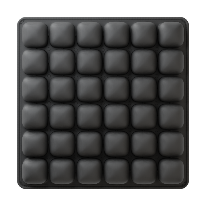
Figure 1: Overcoming Air Valve Base Plate Weld Delamination Under Off-Axis Torquing – Industrial engineering & manufacturing implementation.
2. Engineering Root Causes & Physics of Failure
The root cause of valve weld delamination is severe thermal mass asymmetry during High-Frequency (HF) welding. An injection-molded TPU flange typically has a wall thickness of 1.5mm to 2.5mm, while the mating bladder film is only 0.20mm to 0.40mm thick. Because dielectric heating is directly proportional to material thickness and dissipation factor, the thin film reaches melt temperature long before the thick flange, resulting in a cold adhesive tack rather than a true molecular inter-diffusion weld.
1. The Mechanics of Asymmetric Thermal Mass in HF Welding
When RF energy excites the polymer dipoles, heat dissipation into the cooled upper brass electrode and lower tooling plate creates an uneven temperature gradient. Without custom-tuned stepped electrode geometry or pre-heating of the valve flange, the thin film over-melts and thins, while the thick flange remains below its viscous flow point. Under off-axis user torquing, high peel stresses concentrate at the rigid flange boundary, shearing the cold bond.
2. Annular Stress-Relief Geometry and Flange Tapering
To survive repetitive off-axis loading, the injection-molded flange must feature a gradual feathered edge tapering down to 0.5mm at its outermost circumference. Furthermore, introducing a concentric annular stress-relief groove into the flange design distributes bending moments across a wider radial zone, preventing stress risers from focusing along the weld notch.
3. Durometer Matching Between Flange and Membrane
Specifying a rigid 95A or 98A Shore durometer for the molded valve flange while welding to an 85A flexible film creates an abrupt stiffness mismatch. Under deflection, the flexible film kinks against the rigid perimeter. Matching the flange resin to an 85A–90A formulation restores compliance and improves cyclic peel fatigue life.
3. DFM Parameters & Sourcing Verification Matrix
| DFM Variable | Common Failure Mode | Recommended Engineering Practice | Verification Standard |
|---|---|---|---|
| Flange Edge Profile | Square rigid edge causes severe stress concentration | Feathered taper down to ≤ 0.5mm edge thickness | Optical comparator cross-section |
| Resin Durometer Delta | > 10 Shore A delta triggers localized film kinking | Maintain delta ≤ 5 Shore A between flange and film | Durometer testing per ASTM D2240 |
| Weld Dwell Energy | Cold weld due to flange heat-sinking | Two-stage RF power or conductive lower pre-heat | T-peel test per ASTM D1876 (cohesive film substrate tearing required) |
| Electrode Clamping Face | Uneven pressure across thick molded step | Self-aligning gimbaled upper electrode tool | Prescale pressure-sensitive film mapping |
4. Frequently Asked Questions (FAQ)
Q: What is the minimum acceptable peel strength for a valve weld?
A: While target values depend on chamber pressure and application life-cycles, a sound weld must achieve parent material yield (film tears before the weld seam peels) during ASTM D1876 testing.
Q: Can ultrasonic welding replace HF welding for valve insertion?
A: Ultrasonic welding can attach small ports, but HF dielectric welding remains the industrial standard for large flexible flanges because it heats the entire annular contact surface simultaneously without surface scuffing.
5. Actionable Next Steps for Technical Teams
Submit your current valve assembly CAD to Airjour for a thermal mass balancing and flange DFM assessment.