1. Overview & Engineering Context
High-Frequency (HF) dielectric welding is the benchmark assembly process for hermetic TPU comfort hardware. However, when bladders transition from 2D CAD models to brass tooling, tight corner radii and abrupt chamber intersections become immediate points of failure. Quality teams frequently observe dielectric arcing, burnt film punctures, and notch shear failures concentrated exclusively at sharp internal corners.

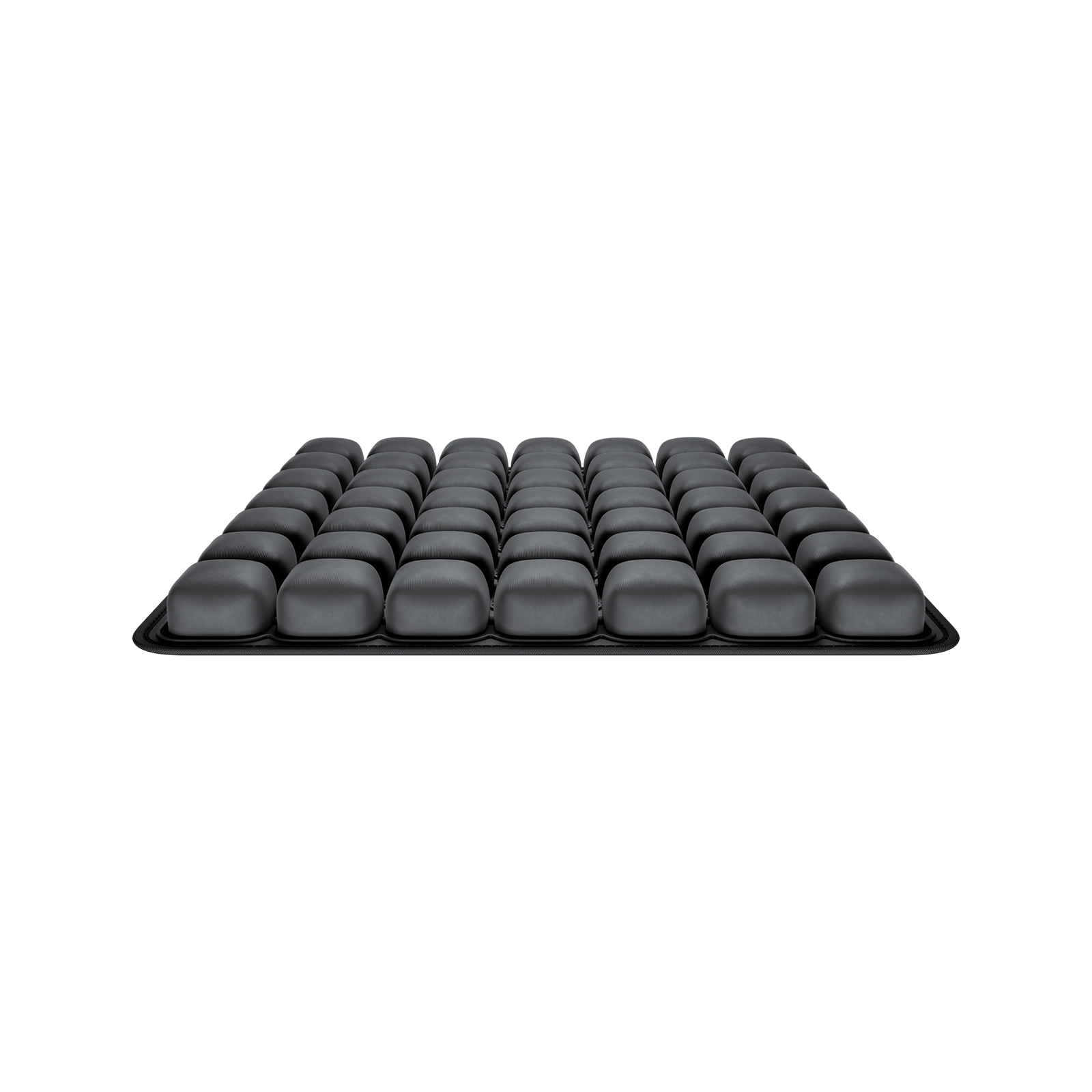
Figure 1: Preventing Corner Dielectric Weld Failures in TPU Comfort Bladders: Radio-Frequency Tooling and Geometry Optimization – Industrial design and quality implementation.
2. Failure Mechanics & Technical Analysis
The root cause is fundamental electromagnetic physics: high-frequency alternating electric fields concentrate at sharp conductive edges and points. When an electrode corner radius is machined too sharp, localized field density exceeds the dielectric breakdown threshold of the molten thermoplastic, ionizing the material and blowing microscopic burn holes directly through the seam.
1. The Physics of Electric Field Concentration at Sharp Tool Radii
The electric field intensity at an electrode boundary is inversely proportional to the radius of curvature. A sharp 90-degree corner with a 0.2mm tool radius produces an intense electric field gradient compared to a smooth 3.0mm fillet. During the weld cycle, this concentration causes localized thermal runaway, vaporizing polymer additives and creating localized pinholes before the rest of the perimeter reaches bonding temperature.
2. Rule Die Machining Tolerances & Chamfer Requirements
Precision CNC-machined brass or aluminum electrodes must maintain minimum corner internal fillets. Tooling engineers must avoid sharp mitered joints on steel-rule dies. Polishing electrode edges to eliminate micro-burrs (which act as miniature lightning rods for dielectric arcing) is an essential tooling sign-off gate before pilot runs.
3. Mitigating T-Junction Thickness Differentials
Where internal structural baffle webs join external perimeter walls, film thickness doubles. Tooling dies without stepped relief exert excessive pressure on the corner transition, mechanically severing the thinner perimeter film while under-welding the thicker core stack.
3. DFM Parameters & Verification Matrix
| Tooling Variable | Critical Failure Mode | Recommended DFM Practice | Inspection Method |
|---|---|---|---|
| Internal Corner Fillet | Field concentration causing dielectric blowout | Design minimum internal radius (R ≥ 1.5 mm fillet to eliminate electric field concentration points) | Optical profile projector / CAD check |
| Electrode Edge Radius | Sharp notch cutting into molten film | Precision radiused sealing lip (e.g., 0.3mm-0.5mm) | Toolmaker surface profilometer |
| Die Surface Roughness | Micro-burrs triggering electrical arcing | Polish to Ra < 0.4 µm along all RF contact faces | Contact surface roughness tester |
| Step-Down Transition | Over-compression at 2-to-4 layer film junctions | CNC stepped-down cavity matching film stack height | Coordinate Measuring Machine (CMM) verification |
4. Frequently Asked Questions (FAQ)
Q: Why do corner leaks occur only under dynamic cyclic loading?
A: A sharp corner creates both an electrical stress riser and a mechanical notch stress riser. Under cyclic inflation or passenger shifting, peel stresses concentrate at the notch apex, initiating fatigue micro-tears.
Q: Can dielectric breakdown be prevented by lowering RF power?
A: Reducing RF power may stop arcing, but it risks creating cold welds along straight seam sections where heat generation is lower. The true solution is proper corner geometry and tooling radius balancing.
5. Next Steps for Engineering & Sourcing Teams
Have Airjour's tooling engineers evaluate your 2D/3D bladder perimeter CAD for RF electrode manufacturability and corner radius compliance.